Automatic Solar Lighting
Published: July 27, 2026
This Year 2 team engineering project involved designing, building, and testing a self-contained outdoor lighting system powered by solar energy. The system generates energy during the day, stores it in a rechargeable battery, and automatically provides lighting when ambient light falls.
The complete design brings together photovoltaic generation, battery charging and protection, voltage regulation, Arduino-based sensing, load switching, and an outdoor enclosure. It was developed as a practical proof-of-concept for pathway, garden, and off-grid lighting applications.
My role: Systems & Electronics Lead. My work focused on circuit design, engineering calculations, electronic component integration, and connecting the theoretical system design to the physical hardware.
📸 Preview
⚙️ System Overview
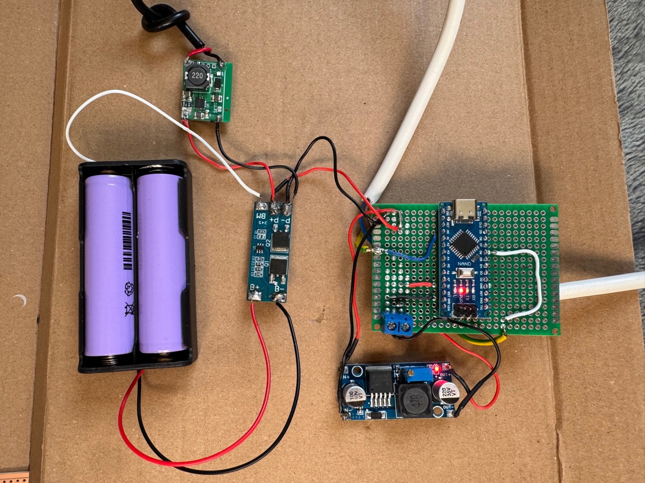
The project was developed in two connected stages: a full 12V outdoor lighting system and a compact Arduino, LDR, and NeoPixel demonstrator used to refine the sensing and gradual-brightness control. The sections below explain how each stage contributed to the final prototype.
Full Outdoor Lighting Design
- A 20W photovoltaic panel converts sunlight into DC electrical energy.
- A 10A PWM solar charge controller regulates the panel output and charges the 12V battery safely.
- The battery supplies the 12V lighting load and also feeds an LM2596 buck converter.
- The buck converter steps the battery voltage down to a regulated 5V supply for the Arduino Nano and sensing electronics.
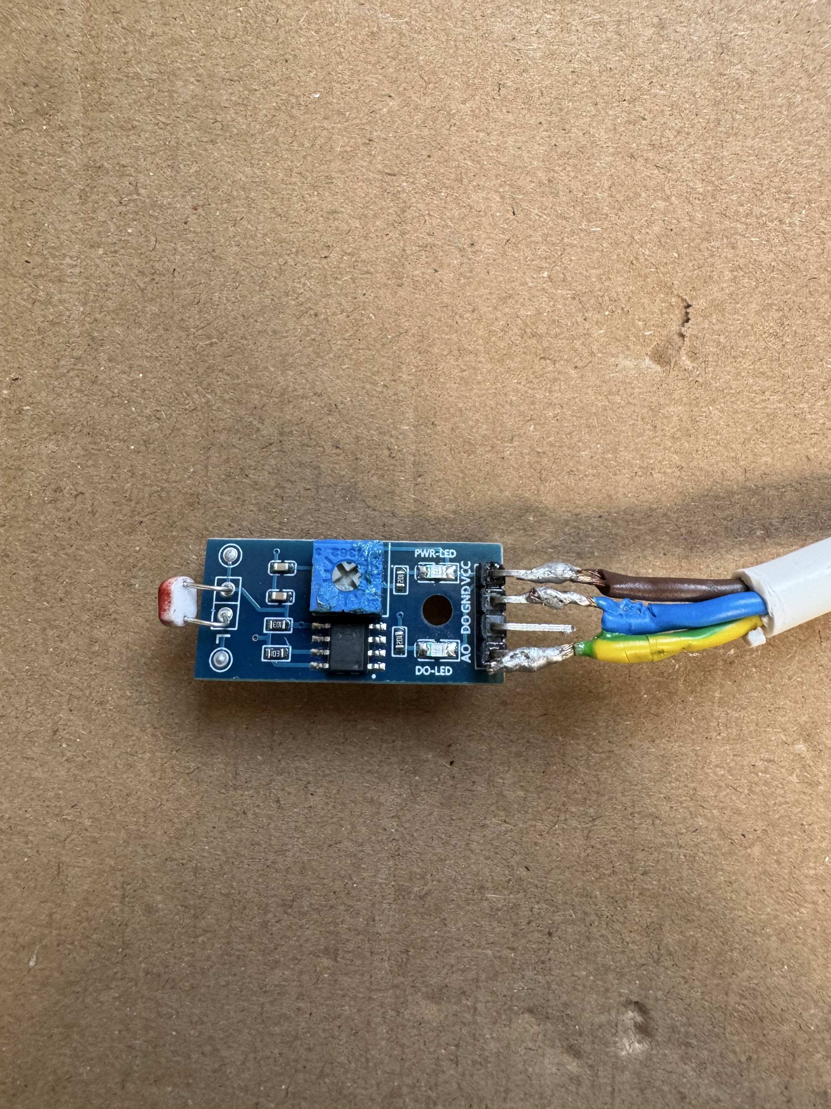
- An LDR module measures ambient light and sends an analogue signal to the Arduino.
- The Arduino applies the control logic and drives a logic-level N-channel MOSFET, keeping the high-current lighting load away from the microcontroller.
- During dusk and dawn, PWM control allows the light output to change gradually instead of switching abruptly.
Arduino Control Demonstrator
- An LDR measures the surrounding light level through analogue pin A0.
- The Arduino maps the sensor reading to a brightness value between 0 and 255.
- The mapped value is constrained to prevent invalid brightness levels.
- The program moves toward the target in three-step brightness increments.
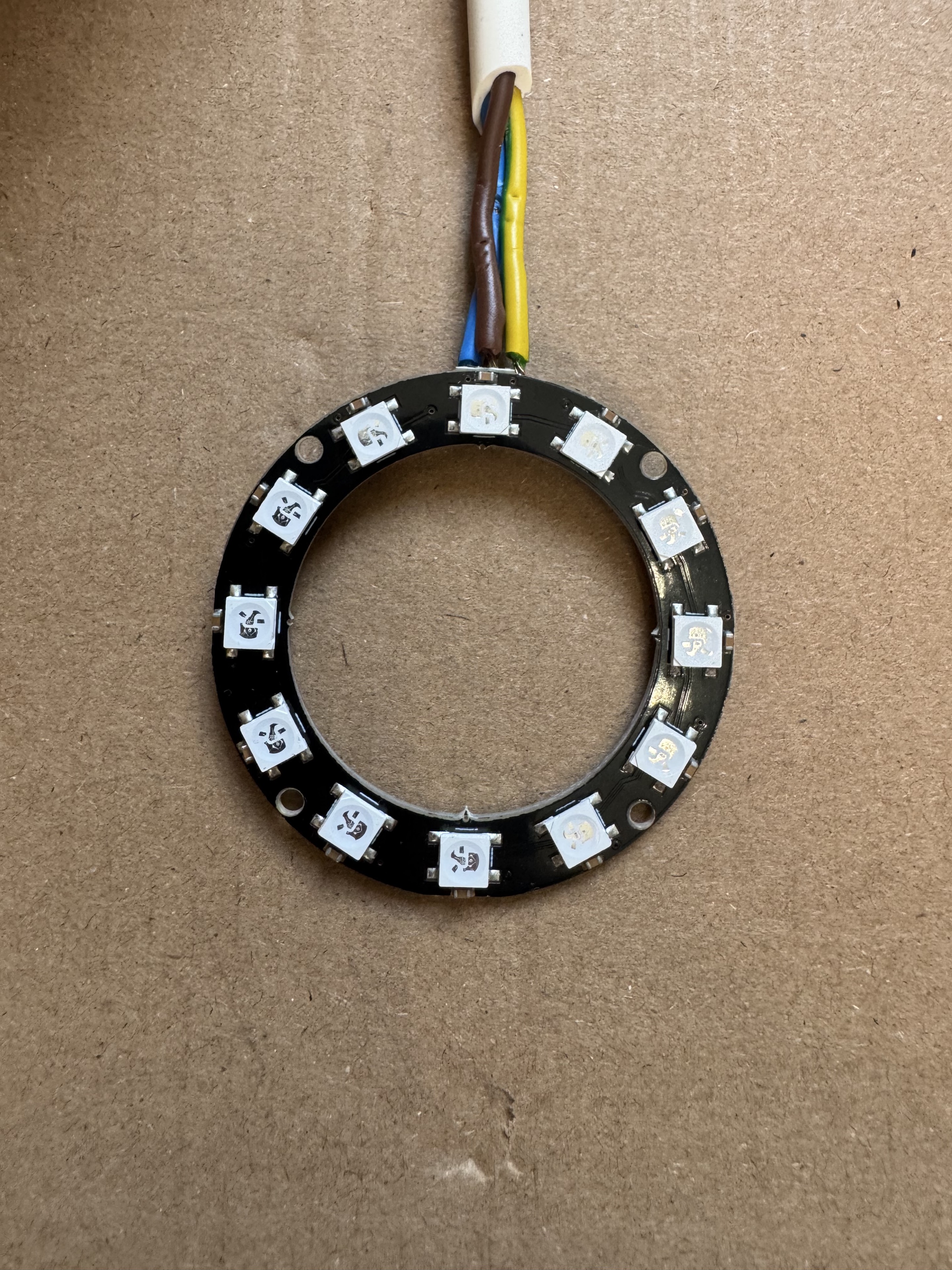
- All 12 NeoPixels display white light at the calculated brightness.
- Sensor readings are printed to Serial Monitor for testing and calibration.
🧰 Full System Components
| Component | Specification | Purpose |
|---|---|---|
| Photovoltaic panel | 20W, 12V nominal | Generates electrical energy from daylight |
| Solar charge controller | 10A PWM | Regulates charging and protects the battery from overcharge |
| Prototype battery | 12V, 7Ah sealed lead-acid | Stores energy for night-time operation |
| Arduino Nano | 5V microcontroller | Reads the sensor and executes the automatic lighting logic |
| LM2596 buck converter | 12V to regulated 5V | Provides a safe supply for the Arduino and sensing circuit |
| LDR sensor module | Analogue output | Measures ambient light for day/night detection |
| N-channel MOSFET | Logic-level, low-side switch | Allows the Arduino to control the higher-current lighting load |
| LED floodlight | 10W, 12-24V DC | Provides the main outdoor illumination |
| Outdoor enclosure | IP65 with cable glands | Protects the electronics from dust and water ingress |
The engineering calculations initially identified a 20Ah SLA battery for greater autonomy. A smaller 7Ah battery was selected for the scaled prototype because of cost, size, and component availability.
🔌 Wiring and Interconnections
Outdoor System
| From | To | Purpose |
|---|---|---|
| Solar panel | Solar charge controller input | Transfers generated solar energy |
| Charge controller | 12V battery | Provides regulated battery charging |
| 12V battery | LM2596 input | Supplies the control-power regulator |
| LM2596 regulated output | Arduino Nano 5V supply | Powers the microcontroller and sensing circuit |
| LDR analogue output | Arduino analogue input | Provides the ambient-light reading |
| Arduino control output | MOSFET gate | Controls the lighting load using PWM |
| Battery, MOSFET stage, and LED | 12V lighting circuit | Delivers switched power to the floodlight |
Control Demonstrator Pin Mapping
| Connection | Arduino Pin |
|---|---|
| 12-pixel NeoPixel data input | D6 |
| LDR analogue signal | A0 |
Critical connections were soldered and insulated with heat-shrink tubing. Terminal blocks were used where appropriate, and 22 AWG wiring was selected for the low-voltage prototype. Power, control, and load wiring were routed separately inside the enclosure to simplify testing and maintenance.
🛠 Build Process
- Design and sizing: The team calculated the lighting demand, battery capacity, and solar-panel requirement before selecting practical prototype components.
- Control prototyping: The Arduino, LDR, and switching circuit were tested on a breadboard before being connected to the final power hardware.
- Power assembly: The panel, charge controller, battery, and LM2596 regulator were connected and checked independently.
- Voltage calibration: The LM2596 output was adjusted and verified with a multimeter before the Arduino was connected.
- Permanent integration: The control electronics were soldered, insulated, and connected to the lighting stage.
- Outdoor assembly: The electronics were installed in an IP65 enclosure with waterproof cable glands and an externally positioned LDR.
✅ Testing and Results
| Test | Measured Result | Outcome |
|---|---|---|
| Solar charging | Battery increased from approximately 12.2V to 13.5-14.0V; sustained charging was approximately 13.8V | Charge controller operated within the expected SLA charging range |
| Night-time runtime | Approximately 6-8 hours, averaging about 6.6 hours across seven nights | Met the scaled prototype target |
| Day/night switching | Approximately 4.5V in bright light, 0.45V in low light, and a 2.5V transition region | Stable automatic switching after threshold tuning |
| Lighting output | Stable brightness with no visible flicker during the runtime test | Power delivery and switching remained stable |
| Outdoor enclosure | No internal moisture, condensation, cable damage, or visible degradation during winter testing | IP65 enclosure and cable sealing passed the test |
Initial false triggering from brief shadows was reduced by refining the light threshold, adding a short control delay, and improving the physical position of the sensor.
📦 Library
| Library | Purpose |
|---|---|
| Adafruit NeoPixel | Controls the 12 addressable LEDs |
🧾 Arduino Control Code
This compact control sketch demonstrates how the LDR reading is converted into a smooth brightness level for the 12-pixel NeoPixel light. The full outdoor system uses the same sensing principle with a MOSFET switching stage for its 12V lighting load.
#include <Adafruit_NeoPixel.h>

#define LED_PIN 6
#define NUM_LEDS 12
#define LDR_PIN A0

Adafruit_NeoPixel strip(NUM_LEDS, LED_PIN, NEO_GRB + NEO_KHZ800);

int currentBrightness = 0;

void setup() {
  strip.begin();
  strip.show();
  Serial.begin(9600);
}

void loop() {
  int ldrValue = analogRead(LDR_PIN);
  Serial.println(ldrValue);

  int targetBrightness = map(ldrValue, 500, 1000, 0, 255);
  targetBrightness = constrain(targetBrightness, 0, 255);

  if (currentBrightness < targetBrightness) {
    currentBrightness += 3;
  } else if (currentBrightness > targetBrightness) {
    currentBrightness -= 3;
  }

  strip.setBrightness(currentBrightness);

  for (int i = 0; i < NUM_LEDS; i++) {
    strip.setPixelColor(i, strip.Color(255, 255, 255));
  }

  strip.show();
  delay(30);
}
👤 My Contribution
As Systems & Electronics Lead, I was responsible for designing and integrating the circuit components, supporting the engineering calculations, and helping translate the planned architecture into a working physical system. This included:
- Planning the power, control, sensing, and load subsystems
- Supporting component selection and electrical sizing
- Integrating the solar, battery, regulation, sensing, and lighting hardware
- Checking voltage levels, polarity, connection integrity, and safe operation
- Supporting prototype assembly, soldering, troubleshooting, and system testing
The software and wider project work were completed collaboratively, with responsibilities shared across the team.
⚠️ Challenges and Safety
- The LDR initially responded to brief shadows and artificial light. Threshold tuning and sensor repositioning produced more stable switching.
- An incorrect buck-converter input polarity was detected with a multimeter before power was applied, preventing component damage.
- Early Arduino soldering created bridges between closely spaced pins. The joints were cleaned, reheated, and reapplied.
- Longer conductors were fitted during enclosure integration to remove mechanical strain from connections.
- The regulator output was calibrated before connection to the 5V electronics.
- Soldered joints, heat-shrink insulation, terminal blocks, cable glands, and battery charging protection were used to reduce electrical and environmental risk.
📝 Limitations and Future Improvements
- The 7Ah prototype battery provided less autonomy than the 20Ah design calculation.
- An LDR is inexpensive and simple but remains sensitive to shadows, reflections, and nearby artificial light.
- The PWM charge controller does not extract as much energy as an MPPT controller under changing irradiance.
- The enclosure passed short-term winter testing, but long-term UV exposure and thermal cycling were not evaluated.
- A future version could add a three-position OFF / AUTO / MANUAL ON switch for isolation, normal operation, and manual fallback.
- Further improvements could include MPPT charging, a larger or higher-energy-density battery, a digital lux sensor, adaptive thresholds, and remote monitoring.